Switchgear panels are used to control, protect and isolate electrical equipment, and high temperatures inside these panels can indicate a fault or failure. During the functioning stage, overheating conditions in electrical switchboards can occur due to some reasons such as overloaded circuits, unbalanced loads, and loose connections, which can reduce the lifespan of equipment and potentially lead to catastrophic failure. Sudden temperature rises of components inside switchboards can also result in burning and melting of components. So here the need of a temperature monitoring system arises.
Continuous temperature monitoring in switchboards is more effective than periodic temperature monitoring because it provides real-time data and allows for immediate detection and response to any temperature fluctuations. This can help prevent damage to sensitive components, reduce the risk of fire, and improve the overall reliability and safety of the electrical system. Continuous monitoring also provides a more comprehensive and accurate picture of temperature trends over time, which can help with maintenance planning and identify potential issues before they become serious problems.
Some of the common locations in electrical switchboards that are prone to hotspots and should be thermally monitored include:
- Bus bar joints
- Cable joints
- Input and output terminals of Circuit Breakers
- Terminals of high-power components (transformers)
- High-load areas (motor control equipment)
- Areas with high ambient temperatures or poor ventilation.
Thermal Image Camera
Thermal imaging camera, also known as a thermal imager or infrared camera, is a device that captures images using thermal radiation, or heat, emitted by objects. These cameras convert thermal radiation into visible images that can be used to identify areas of high temperatures, such as hot spots, leaks, or faults in electrical and mechanical systems. They provide non-contact, real-time temperature measurement, making them a useful tool for troubleshooting, predictive maintenance, and condition monitoring. It can be taken as a method of periodic temperature monitoring.
Pros
- Highly sensitive and can detect small temperature variations
- Non-contact measuring device
Cons
- Relatively expensive
- Limited range of measurements with accuracy
- Humidity and dust particles affect to the accuracy
- Readings are based on the person who use the camera and needs a training to use it.
Thermocouple
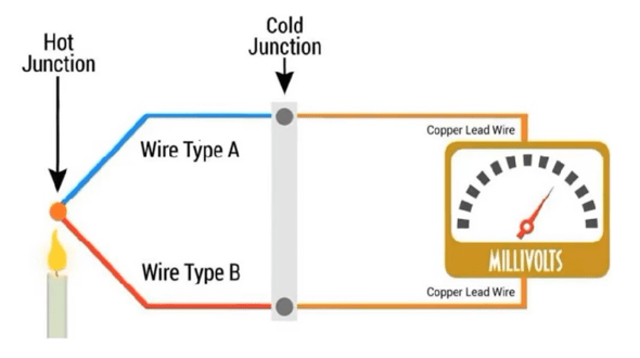
Thermocouple is a type of temperature sensor that uses the principle of the thermoelectric effect to measure temperature. It consists of two wires made of different metals that are joined together at one end, and the other end is exposed to the measuring system.
Pros:
- Fast response
- Simple and rugged
- Less expensive than other sensors
Cons:
- Low accuracy
- Non-linear variation of output
- Very low voltage output
RTD (Resistance Temperature Detector)
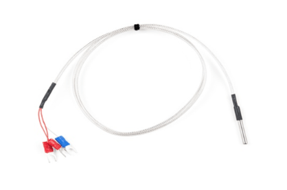
An RTD is a type of temperature sensor that uses the principle of electrical resistance to measure temperature. It typically consists of a thin film or wire made of a material (mostly platinum) that has a predictable change in resistance with temperature. Its resistance proportional to the temperature and has almost linear variation. The most common sensors are pt100 & pt100 (pt100 means 100 Ohms resistance at 0 0C). In this case, a Signal isolator is used to supply the galvanic isolation from the mains voltage and converts the resistance value to a 4-20mA signal or any other readable manner. The value can be read by a plc or any other compatible device.
Pros
- Directly measures the temperature of the required point
- Reliable and precise measurement
cons
- Power surges and unintentional short circuitscan harm the whole measuring system
- Cost depends on the quality of the isolator
Infrared Temperature Sensors
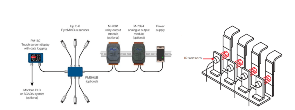
Infrared temperature sensors can also be used for busbar temperature monitoring, which are non-contact, can measure temperature from a distance, and can be useful in high-temperature or hazardous environments. The Infrared (IR) Sensor can detect a specific range of IR rays, typically within the range of 0.7 μm to 20 μm (The IR spectrum ranges from 0.7 μm to 1000 μm). The amount of IR radiation emitted is proportional to the temperature of a surface, as per the theorems of black body radiation. But the surface of the measurement must be non-reflective for accurate measurements. In the case of measuring busbar temperature, it is recommended to use a non-reflective sticker at the point of measurement to prevent the reflection of IR rays, which could result in incorrect readings. The core of the IR sensor is made from a silicon chip with a series of thermocouples that are capable of detecting the IR spectrum.
Measuring System
How Sensors are connected to the Busbar
Pros
- The measurement method is non-intrusive
- Reliable measurements when installed correctly
- High response time
- The measurement system is protected from voltage surges and short circuits
Cons
- Reflections from metal parts may reduce the accuracy
- High cost – Expensive than RTDs
Surface Acoustic Wave (SAW) Sensors
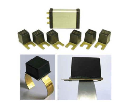
Surface acoustic wave sensors consist of two parts. SAW Transponder and Reader Unit. SAW transponder is the sensing part and it is connected directly to the busbar. SAW Transponder has two antennas called interdigital transducers (IDT). IDTs are placed on a piezoelectric substrate. Two antennas are placed at a defined distance. One antenna works as a receiver and another one works as a transmitter. The space between two sensors is called the delay line. The antennas are sensitive to RF signals (Usually 2.45GHz). The reader sends an RF pulse and the transponder antenna detects it. Then the RF signal converts into a surface acoustic wave called Rayleigh wave. That wave propagates through the delay line and converts to an RF signal again by the transmitter antenna. Due to temperature differences, the length of the delay line changes because of thermal expansion. Therefore, the response time, frequency, and phase angle can be changed according to the temperature. By measuring these parameters of the response signal by the transponder. The reader can identify the temperature of the busbar. This method is intrusive. But wireless. Therefore, the sensor can be connected anywhere on the busbar regardless of access.
Pros
- Directly connected to the busbar, directly measures the parameter
- It can be connected to places where access is limited
- Stable and reliable measurement
- No batteries or power needed to power the sensors
- Power surges and short circuit will not break the whole measuring system
Cons
- Cost of the system is high
Energy Harvesting Type Temperature Sensors
In the sensor, there is a temperature measuring probe on board. Which directly measures the temperature of the busbar. Energy for the sensor power is harvested from the busbar itself via Electromagnetic Induction using an internal coil or a ferromagnetic ribbon. The measured value is transmitted via an RF wave (Usually 2.4Ghz signal) to a reading module which will outputs a readable communication signal like Modbus.
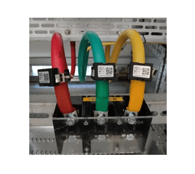
Engineers can analyze the readings getting from sensors via Modbus communication by plotting graphs against time. This allows for real-time monitoring and analysis of the sensor data, enabling engineers to quickly identify trends, patterns, and any potential issues within the network.
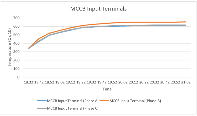
An example graph of Temperature rise against time for MCCB incoming terminals
Wireless temperature monitoring can be particularly useful in industries such as power generation, oil and gas, and manufacturing, where equipment failure can have significant consequences.
So the best solution for a sensor for any specific application will depend on several factors such as cost, accuracy, durability, and environmental conditions. Wireless temperature monitoring techniques are the most suitable for continuous and wireless real-time temperature monitoring specially in switchboard applications.
