Harmonics play a significant role in the world of electrical power systems. They are integer multiples of the fundamental frequency and are responsible for shaping the quality of electrical waveforms. The fundamental frequency from the power grid is mostly 50Hz and 60Hz, also known as the ‘1st Harmonic.’ As we move up the harmonic series, the 3rd harmonic occurs at three times the fundamental frequency (150Hz), the 5th harmonic at five times the fundamental frequency (250Hz), and so on.
The combination of harmonics with unique amplitudes and phase angles results in what is known as ‘harmonic distortion.’ This distortion leads to the creation of non-sinusoidal waveforms, which can have significant consequences on the performance and efficiency of electrical equipment.
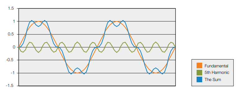
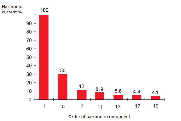
Each harmonic component contains a magnitude and phase angle, which determines its impact on electrical installations. Typically, lower-order harmonics have greater amplitudes, making them more influential in distorting waveforms.
Understanding harmonics and harmonic distortion is crucial for engineers and technicians in the field of electrical power systems. It enables them to diagnose and mitigate issues related to harmonic distortion, ensuring stable and reliable operation of electrical installations. By managing harmonics effectively, we can maintain the integrity of power supply and avoid problems such as overheating of equipment, interference with sensitive electronics, and increased energy losses.
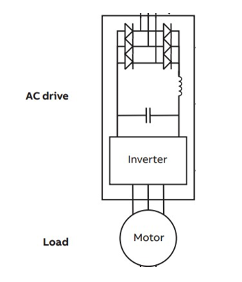
In a VSD, the output waveform is typically a pulse-width-modulated (PWM) waveform. The PWM waveform consists of a series of voltage pulses at a high switching frequency, which is typically much higher than the fundamental frequency. The switching frequency is often referred to as the carrier frequency.
The harmonic content of the PWM waveform depends on the carrier frequency and the modulation index. The modulation index represents the ratio between the amplitude of the desired fundamental frequency component and the maximum possible amplitude of the PWM waveform.
In a well-designed VSD, the carrier frequency is chosen to be much higher than the desired harmonic frequencies. As a result, the harmonics generated by the VSD fall outside the range of the dominant harmonics.
Harmonic order = nk ± 1
Where n is an integer and k is the pulse index. (Number of diodes)
The modern 3 phase VFDs are having 6 pulse, 12 pulse, 18 pulse, 24 pulse and etc. Thus as per the following example it can be seen that with the 6 pulse index VFDs how the harmonic generation is taking place.
H = n * (6) ± 1
When n=1,
H = 5 and 7
When n=2,
H=11 and 13
When n=3,
H=17 and 19
And so on.
Can a modern 3 Phase VSD generate 3rd Harmonic?
Since the modern motor drives are consisting 6 pulse and upward drives, as per the above equation it can be conclude that 3rd harmonic can’t be generated in the 6 pulse VSD and the generated harmonics would be odd harmonics from the 5th harmonic onwards. If it is a 12 pulse drive generated harmonics would be 11th harmonic onwards.
Even though it is expected in that manner the following diagram shows that there would be 3rd order harmonics recorded at the incoming side of the VSD. These are actual records that captured when a 6 pulse drive is running a motor load. There are even order harmonics below 0.1% and the 3rd harmonic level at 0.2% which is considerably low compared to the 5th, 7th and higher order odd harmonics which can be generated as per the above equation.
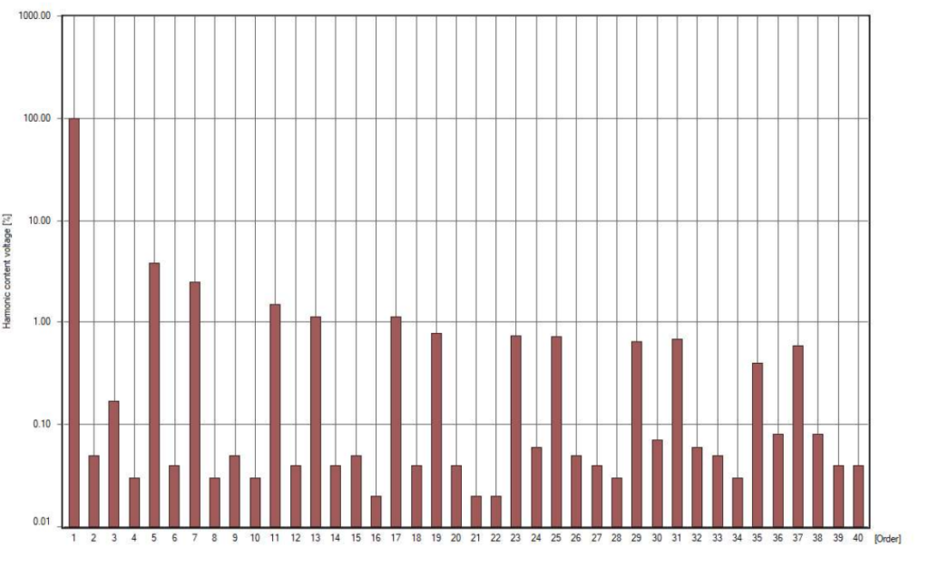
However, it is evident that 3rd harmonics can still be present in the VSD output due to non-idealities in the VSD circuitry and interactions with the power system. While the 3rd harmonic might not be generated directly by the VSD, it can still be present as a result of interactions with other loads or system components. As per the obtained results we can conclude that that 3rd harmonic component is negligible compared to other higher order odd harmonic levels.
Further the magnitude of these harmonics decreases as the harmonic order increases, following a harmonic decay pattern.
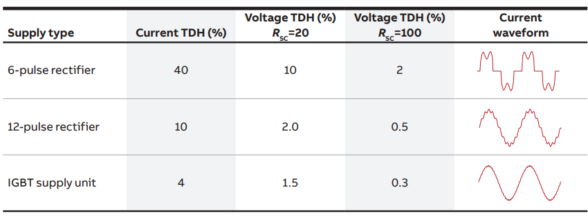
Replacing the diode rectifier unit with an IGBT supply unit (ISU) offers numerous advantages and possibilities over traditional diode bridge rectifiers. The converter circuit, being an active supply unit, exhibits minimal harmonics at lower frequencies, while slightly higher harmonics at higher frequencies. This characteristic grants the ISU the capability of both rectification and regeneration, allowing independent control of DC-voltage level and displacement power factor, irrespective of the direction of power flow.
The following graph shows how much current harmonics are produced by different setups of: 6 pulse, 12 pulse and the active supply unit (ASU) drive. It’s clear from the graph that using an Active Supply Unit can reduce harmonic generation in the drive system compared to diode rectifier drive.
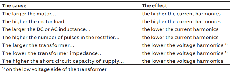
Further the following table shows the cause and effect of the different factors that are affecting for diode rectifier drive system,
References:
- https://library.e.abb.com/public/bc35ffb4386c4c039e3a8ec20cef89c5/Technical_guide_No_6_3AFE64292714_RevF_EN.pdf
- https://www.nhp.com.au/-/media/Project/NHP/Sites/Shared/WhitePapers/Files/NHPTNL64.pdf