PROCESS OF SELECTING THE CORRECT BUSBAR SUPPORTS AND IT’S IMPORTANCE
Importance of Busbar Supports in LV Switchgears
Busbar supports play vital role in Low Voltage switchgears. Main idea is to hold and provide insulation to conductive busbars, which carry electrical currents inside the switchgear. These busbar supports secure the spacing between them and the proper alignment, avoiding any accidental contacts or minimizing the risk of short-circuits or arcing. Also, busbar supports provide mechanical stability to the switchgear structure by decreasing the risk of misalignment and sagging of the busbars. When it comes to the maintenance, proper arrangement of busbar supports can provide ease of maintenance, by allowing access to the busbars for inspection or maintenance procedures. This will ensure the low downtime securing the continuous operation of the electrical system. So, as we can see busbars contribute to the safety, reliability and longevity of the electrical system by providing proper insulation, mechanical support and facilitating maintenance activities for the Low Voltage switchgears.
Selection of Busbar Supports in LV Switchgears
Electromagnetic Effect on Rigid Conductors
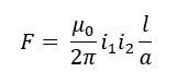
When currents are flowing through conductors, electromagnetic forces are induced in them. As we know, when current flows in the same direction in two conductors, forces will be attractive and when current flows in opposite directions in two conductors, forces will be repulsive. Those electromagnetic forces cause stresses on the parallel conductors. For the calculations, only the electromagnetic forces between parallel conductors will be considered, and electromagnetic forces due to the bends and/or crossovers can be neglected. Also, when considered parallel conductors are long compared to the distance between them, those forces will be evenly distributed along the conductors.
Rigid Conductor Arrangements
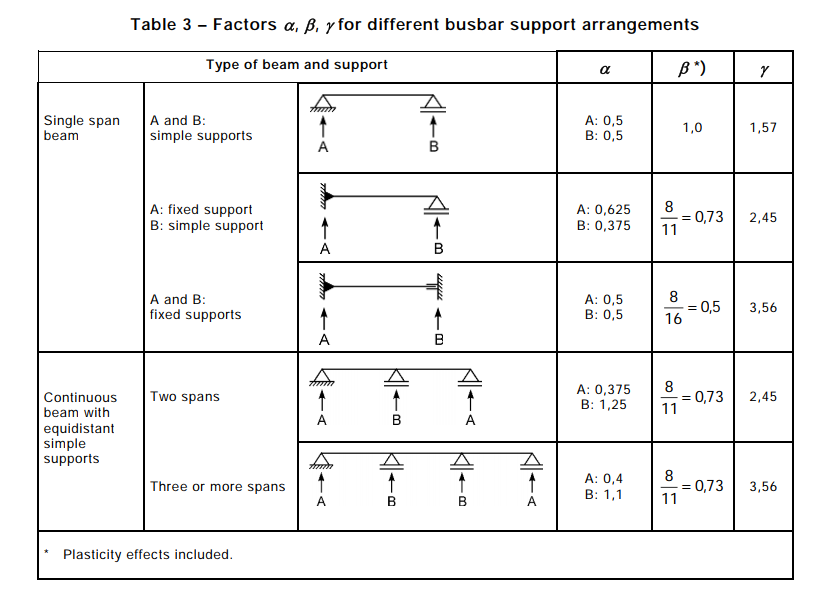
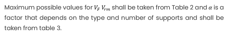
There are several ways to support the rigid conductors. Either they can be fixed supports, simple supports or a combination of both types. However, for the same short-circuit current, stresses in the conductors will be different due to the type of the support and the number of supports. Also, ratio between the natural frequency of the mechanical system and the electrical system is a key factor when it comes to the stresses in the conductors and forces on the supports. When there is a scenario of resonance of near point to the resonance, these stresses and forces can be amplified.
Following terms will be used in the latter part of this article.
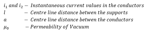
Main Conductor – Conductor or arrangement composed of a number of conductors which carries the total current in one phase.
Sub-Conductor – Single conductor which carries a certain part of the total current in one phase and is a part of the main conductor.
Fixed Support – Support of a rigid conductor in which moments are imposed in the regarded plane.
Calculation of Electromagnetic Forces
Calculation of short-circuit currents should be based on IEC 60909. According to IEC 60865-1-2011, this calculation can be divided in to three scenarios as follows,
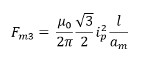
I. Calculation of peak force between the main conductors during a three-phase short-circuit
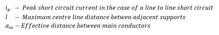
II. Calculation of peak force between the main conductors during a line-to-line short-circuit
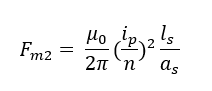
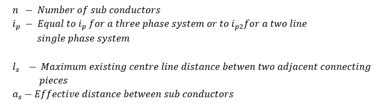
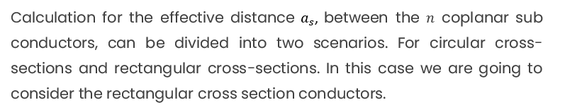
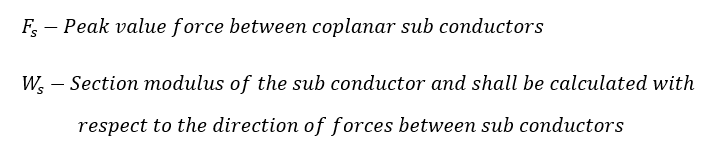
III. Calculation of peak value force between coplanar sub-conductors
Calculation of Stresses in Rigid Conductors
According to the IEC 60865, we are going to assume that forces which are acting on the supporters are bending forces and for that conductors should be fixed, so that axial forces can be neglected. As we know bending force is a force that applied to the length of the material. This can be applied to a point, area or volume which is some distance from a fixed part of the component. Severe bending forces can cause material failures.
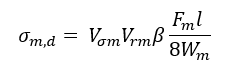
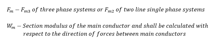
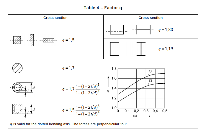
Bending stress cause by the forces between main conductors,
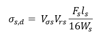
Bending stress cause by the forces between sub conductors,
Permitted Conductor Stress
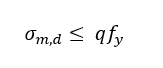
Single conductor can withstand the short-circuit forces when,
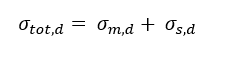
When a main conductor consist of two or more sub-conductors, the total stress in the conductor can be calculated using,
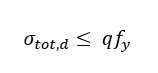
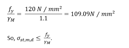
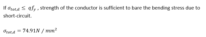
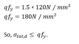
The conductor can withstand the short-circuit forces when,
According to the IEC-60865-1, it is necessary to verify that short-circuit does not affect the distance between sub conductors too much, therefore following is recommended.
It is important to note that, static stress due to dead load of the conductor shall be combined with the stresses due to short-circuit corresponding to the direction of the action.
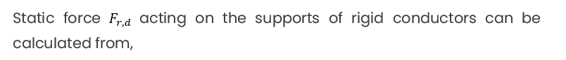
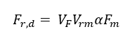
Structure Loads due to Rigid Conductors
Example Calculation:
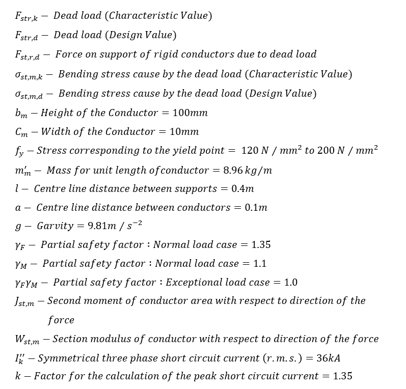
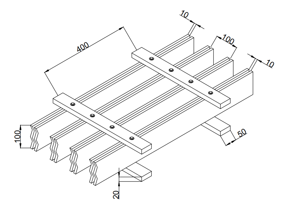
Let’s consider a 3Ø, 400V 2500A busbar system with two conductors per phase. Symmetrical three phase short-circuit current (r.m.s.) is considered as 36kA. Conductors are continuous beams with equidistant simple supports. Calculation is done considering two scenarios. First scenario is the normal load case, due to the dead load of the busbar and second scenario is the exceptional load case considering the combination of effects of the short-circuit current and dead load. Considered conductor arrangement as follows.
Symbols & Data:
A. Normal Load Case : Conductor Stress and forces on the supports due to dead load
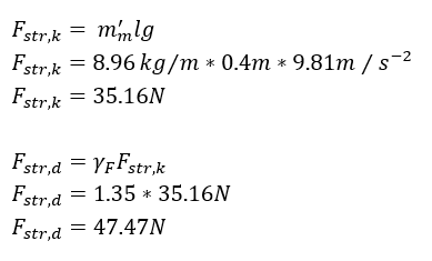
Dead load on the conductor is:
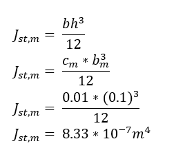
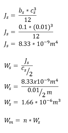
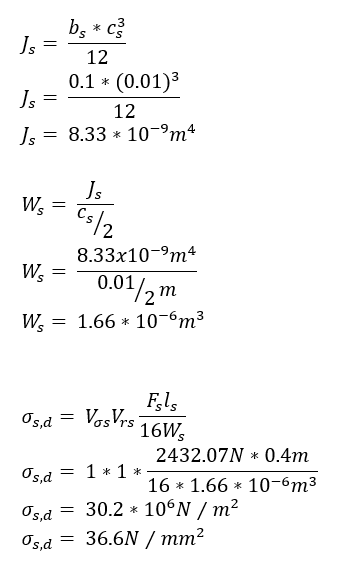
Second moment of inertia of the conductor:
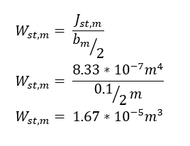
Section modulus of the conductor:
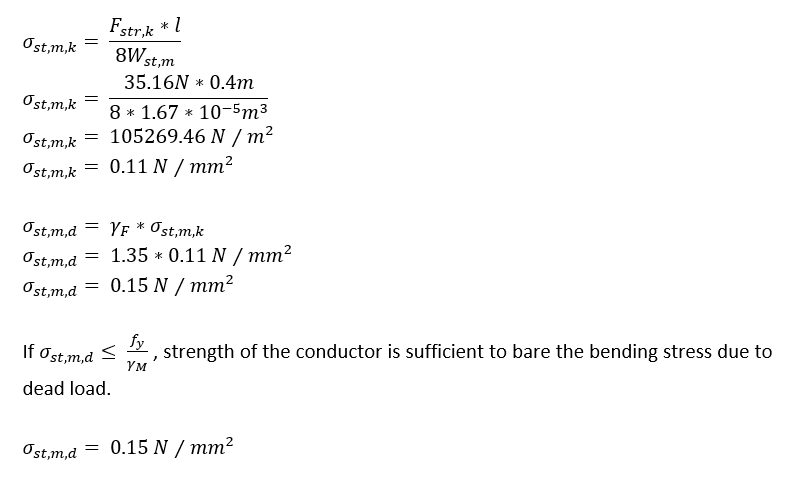
Conductor bending stress due to dead load is:
And
Forces acting on the supports are in the direction of the dead load,
Outer Supports (A):
Outer Supports (A):
B. Exceptional Load Case : Conductor Stress and forces on the supports due to short-circuit currents
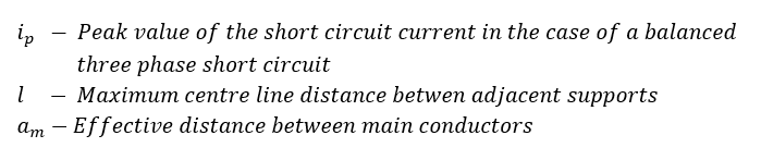
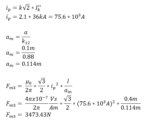
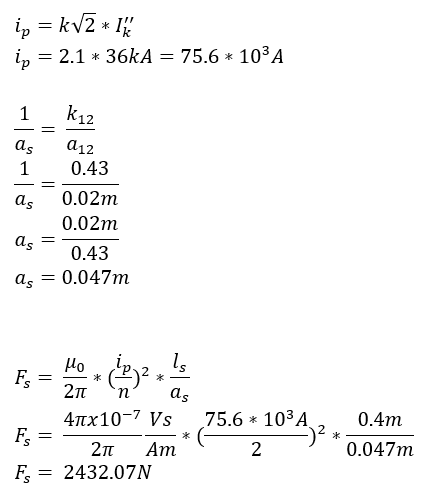
Maximum electromagnetic force on the central main conductor,
Maximum electromagnetic force on the sub-conductor,
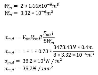
Maximum bending stress caused by the forces between the main conductors,
Maximum bending stress caused by the forces between the sub-conductors,
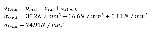
Total conductor stress,
And
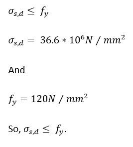
And also, it is recommended that bending stress due to the forces between sub-conductor holds,
Forces on the supports,
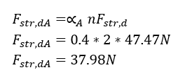
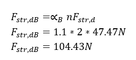
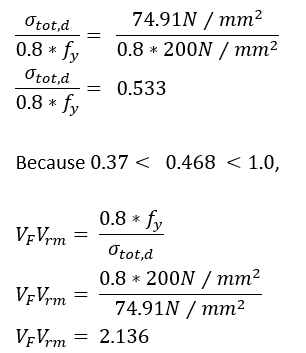
Equivalent static force on supports,
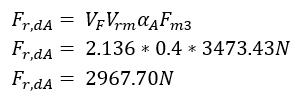
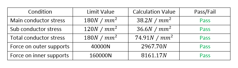
For the outer supports,
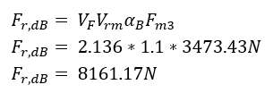
For the inner supports,
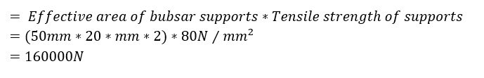
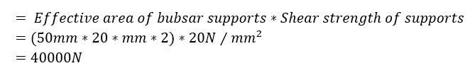
Mechanical withstand capability of inner supports,
Mechanical withstand capability of outer supports,